

Need help choosing the right product?
Our tool will match the best product to your needs
Launch product selectorWelcome to the USA Website
We have detected that you may prefer the Global site. Please use the language dropdown above to change your selection if required.
1. Characteristics of silicon carbide heating elements:
1.1 Construction
Silicon carbide is a ceramic material with relatively high electrical conductivity when compared to other ceramics. Elements are produced by pressing or extruding and then sintering.
Typical heating elements are rods or tubes, with diameters between 0.5 and 3 inches and lengths from 1 to 10 feet. They have metalized ends for electrical connections, and they often have both connections at one end, with two helical slots which stop short of the other end, thus approximating a twisted hairpin form.
Typical heating elements are rods or tubes, with diameters between 0.5 and 3 inches and lengths from 1 to 10 feet. They have metalized ends for electrical connections, and they often have both connections at one end, with two helical slots which stop short of the other end, thus approximating a twisted hairpin form.
1.2 Electrical characteristics
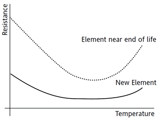 The resistance of these elements varies with both temperature and time. The nature of these variations depends on the particular grade of material and manufacturer. For most types, the resistance is high when the material is cold, decreasing as temperature rises, reaching a minimum at typically between 1000°F and 2000°F, then increasing again as its temperature rises further. When kept at a high temperature, the resistance of the material increases with age.
The change in resistance can be of the order of 3 or 4 to 1 for both timerelated and temperature-related phenomena, giving an over-all ratio of the order of 10:1.
The rate of ageing is affected by the surrounding atmosphere, and also depends to a large extent on the operating temperature (and hence on the power being dissipated). Most will quote life related to maximum power in various temperatures and atmospheres.

2. Control requirements
A control system for silicon carbide heaters should ideally provide means for:
Dealing with the wide variation of resistance
Keeping the power dissipated below the specified maximum at all times
Four different methods are described below:
2.1 Contactor and multi-tapped transformer
This is the traditional method used for controlling silicon carbide heaters. It is included here only for comparison with the SCR methods.
In this system the power is switched by a contactor and the voltage applied to the heaters is adjusted manually by means of multi-tap transformers, ammeters and voltmeters. It is necessary to measure and adjust the currents and voltages regularly and frequently (by manually changing the transformer connections). This method can compensate for the change of resistance due to ageing, but it is not a practical solution to the resistance changing with temperature.
2.2 Voltage control with fixed current limit (Figure 2)
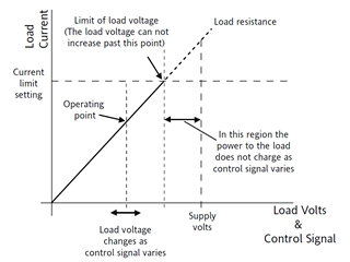 This method can provide some degree of automatic comparison for variation of load resistance. The SCRs are triggered in the “phaseangle” mode, and there are two internal control loops: voltage control and current limit. The voltage control loop is designed to keep the mean square of the voltage applied to the load proportional to the control signal. The current control loop can override the voltage control loop, and is designed to prevent the RMS value of the current from exceeding a fixed level (irrespective of control signal). This has also been called “Threshold Current Limit”.

2.3 Voltage control with proportional current limit (Figure 3)
The SCRs are triggered in the “phase-angle” mode and there are two internal control loops: voltage control and current control. The voltage control loop is designed to keep the mean square of the voltage applied to the load at a level corresponding to the control signal. The current control loop is designed to keep the RMS value of the current at a level corresponding to the control signal. The transition from voltage control to current control occurs at a particular value of load resistance, which is determined by the setting of the “current limit” potentiometer. This has also been called “V/I Transfer” control and “Linear Current Limit”.
2.4 True-power control with current limit (Figure 4)
The SCRs are triggered in the “phase-angle” mode, and there are two internal control loops: power control and current control. The power control loop is designed to keep the mean power (volts x amperes) supplied to the load at a level corresponding to the control signal. The current loop can override the power control loop, and is designed to prevent the RMS value of the current from exceeding a fixed preset level (irrespective of control signal).

3. Choice of Control Method:
The choice of which method to use depends on several factors and, of course, it probably requires a compromise between performance and price.
3.1 The ”Contactor and Transformer” method has little to recommend it.
The initial cost of the multi-tap transformer and wiring is high and it requires considerable time, effort, and skill to maintain the correct adjustment manually. It compensates for only the resistance change due to ageing, so the system must be designed to provide enough heat when the resistance is maximum without over-powering the elements when the resistance is minimum. Incorrect adjustment (due to human error or forgetfulness) can cause the heaters to dissipate more than the permitted maximum power or less than the required power, resulting in shortening of element life or inability to achieve the required temperature.
3.2 “Voltage Control with Current Limit” appears to be the simplest SCR method, however it requires great care and several difficult choices to be made in the system design.
Figure 5 illustrates the problems. It shows “load lines” corresponding to the maximum and minimum resistances of a typical silicon carbide element on a current versus volts graph, with a power curve corresponding to the maximum permissible power specified for the element. In order to prevent excessive power, the operating power must be below and to the left of the “Heater power limit” curve at all times. Therefore the current limit must be set to the values corresponding to the power limit at the supply voltage (shown as point A in Figure 5). If the current limit and supply voltage are set to give full power (heater power limit) at the maximum resistance (point B in Figure 5), at all other values of resistance the available power will be less than the power limit and so larger heaters will be needed to reach the required temperature.

A similar problem exists if the minimum resistance is chosen to be “full-power” value (point C in Figure 5). (In this case, of course, current limit would be unnecessary.) The best solution (using voltage control with current limit) will be compromise (such as A in Figure 5) which will minimize the size of heater required while still providing enough power to reach the required operating temperature. The operating point will always be within the area denoted by 0EAD in Figure 5. Point A should be as close as possible to the maximum operating temperature (assuming that this temperature requires maximum power) but that resistance changes during the life of the element! So the point chosen should represent the mean resistance at maximum operating temperature over the expected life of the element. In practice the available supply voltage or transformer voltage will probably not coincide with this chosen point (A in Figure 6) and so a different point, close to A, will be used. This is shown as Q in Figure 6.

3.3 Choice of which type of current limit to use
Either type of current limit may be used in the system described in 3.2, but proportional current limit is much better than fixed current limit. The following is an explanation of why this is so.
Fixed Current Limit works well with those types of heaters whose resistance increases with rising temperature, such as tungsten, because the current limit operates only when the temperature is low and the controller is calling for maximum power. Such a system should be designed so that the supply voltage and current limit setting interact at the point on the maximum power curve corresponding to the maximum resistance (point B in Figure 5).
When the resistance of those heaters is low, so is the temperature and hence the heat loss so that the power available (reduced by current limiting action to a fraction of the power limit) is still sufficient to raise the temperature. As the temperature increases, the available power increases and so automatically compensates for the increasing heat loss. By the time the operating temperature is reached and the temperature controller is reducing the power demand, the current limit is no longer being used.
When fixed current limit is used with silicon carbide elements (at least when new) it is likely that the resistance will be close to the minimum when the load reaches operating temperature, so that the current limit will be operating as the temperature approaches setpoint. This means that there will be a discontinuity in the proportional band at the point of transition from voltage control to current control, and the point of transition changes with changing signal. Within this region the current-control signal has no effect (until the point of transition reaches the operating point). This will be certain to cause “overshoot” when setpoint is reached. Also the reduction of resistance causes an increase in loop-gain, so that if the control loop was tuned when the resistance was cold it may begin oscillating as it heats up. Unfortunately, any increase in proportional band to compensate for this will increase the overshoot.
Thus proportional current limit is better than fixed current limit because proper control action is maintained throughout the proportional band. The operation simply transfers between voltage and current control as the load resistance passes the critical value (represented by the 0Q in Figure 6). There is no discontinuity in the proportional band, and the variation in loop-gain is much less than fixed current limit.
It should be noted that voltage control, with either fixed or proportional current limit, suffers from the disadvantage that the maximum permissible power dissipation can be achieved at only one value of load resistance (represented by 0A in Figure 5 and 0Q in Figure 6). At any other value of load resistance the maximum power available must be lower, so that the heater required is larger than that implied by the specified power limits.
3.4 “True-power Control with Current Limit”
True-power control has the ability to reach the maximum permissible power level at all values of load resistance. This enables smaller heaters to be used in many applications.
As illustrated in Figure 7, the supply voltage and current limit setting can be set at or near the limits of the resistance range, thus allowing full power (i.e. maximum permitted power) to be dissipated at all possible values of resistance. Note also that current limit is not necessary for normal operation; it serves only to protect against faults such as incorrect connections when changing elements.
4. Design Procedure
To optimize the design of a system using silicon carbide elements it is likely to be necessary to repeat the calculations with different elements, different supply voltages, etc. Thus by a process of iteration the best combination for the particular application can be found. Eurotherm has developed software tools to assist engineers in the optimization of power control systems, the calculation of top voltage on transformer and thyristor current ratings. Appendix 1 shows a table with examples of designs for several different applications.
Warning
Elements connected in series and/or parallel will not dissipate equal amounts of power unless their resistances are identical. Therefore such elements should be replaced as a set. It is unlikely that these elements will age, or heat up, at the same rate, and therefore the life of the set may be reduced due to over-powering of one element. This problem can be avoided by providing a separate power controller for each element.


Product Selector
Our tool will match the best product to your needs
Launch product selectorContact Us